We’ve built ARINC 825-4 and CAN Bus (CAN FD) solutions for avionics and defense programs for more than twenty-five years, so what follows comes from interfaces that have flown, not from a datasheet read once.
TL;DR Quick Answers
ARINC 825-4 and CAN Bus (CAN FD) solutions
ARINC 825-4 and CAN Bus (CAN FD) solutions are the IP cores, transceivers, and board-level products that put avionics-grade CAN onto aircraft, defense, and vehicle data buses. ARINC 825-4 is the avionics CAN standard (currently at Supplement 4) built on classic CAN, and CAN FD raises the data phase to 4 Mbit/s with 64-byte payloads.
ARINC 825-4: the avionics higher-layer CAN standard, built on CAN 2.0B, with Supplement 4 adding CAN FD. It defines the messaging structure, logical communication channels, and 11-bit and 29-bit identifiers aircraft systems use.
What CAN FD adds: it keeps classic CAN's arbitration phase but lifts the data phase to 4 Mbit/s and stretches payloads from 8 to 64 bytes, so a busy bus moves far more in every frame.
What "solutions" means: CAN, CAN FD, and ARINC-825-4 IP cores delivered as a vendor-independent VHDL netlist for any FPGA or ASIC, plus CAN transceivers, physical-layer products, and boards and testers, all working with any COTS transceiver.
What sets the best ones apart: a standard CAN controller only moves data. A secure core also watches the bus it sits on, authenticating every node, flagging spoofed messages, and locating wire faults with distance-to-fault.
Certifiable for avionics: built to DO-254, with DO-178 for associated software, and certifiable up to Design Assurance Level A.
Top Takeaways
ARINC 825-4 builds on the Controller Area Network (CAN) standard, keeping CAN FD’s arbitration phase and adding avionics messaging over it.
Two bit rates mean two sets of hardware demands. The fast data phase, not the arbitration phase, drives your transceiver, termination, and layout choices.
Terminate 120 ohms at both far ends only, keep a linear bus with short stubs, and reach for SIC transceivers when the topology fights you.
Budget bit timing, oscillator tolerance, and propagation delay for the rate you’ll actually run. At 4 Mbit/s the margin is thin.
Isolate, protect, and qualify for the airframe, then design to DO-254 so the interface can certify up to DAL A.
From Classic CAN to CAN FD to ARINC 825-4
Three protocols stack here, and each one asks more of the wire than the last. Classic CAN (CAN 2.0B) gives you arbitration-based messaging with 29-bit identifiers, rates up to 1 Mbit/s, and an eight-byte payload. CAN FD keeps that arbitration but pushes the data phase to 4 Mbit/s and stretches the payload to 64 bytes, so a busy network moves far more in every frame. ARINC 825-4 sits on top and adds the avionics messaging discipline aircraft need, including logical communication channels and the addressing scheme that keeps traffic deterministic. The hardware takeaway is short. The moment two bit rates share one bus, the slow arbitration phase and the fast data phase want different things from every part on the wire.
Transceiver Selection for the Data Phase
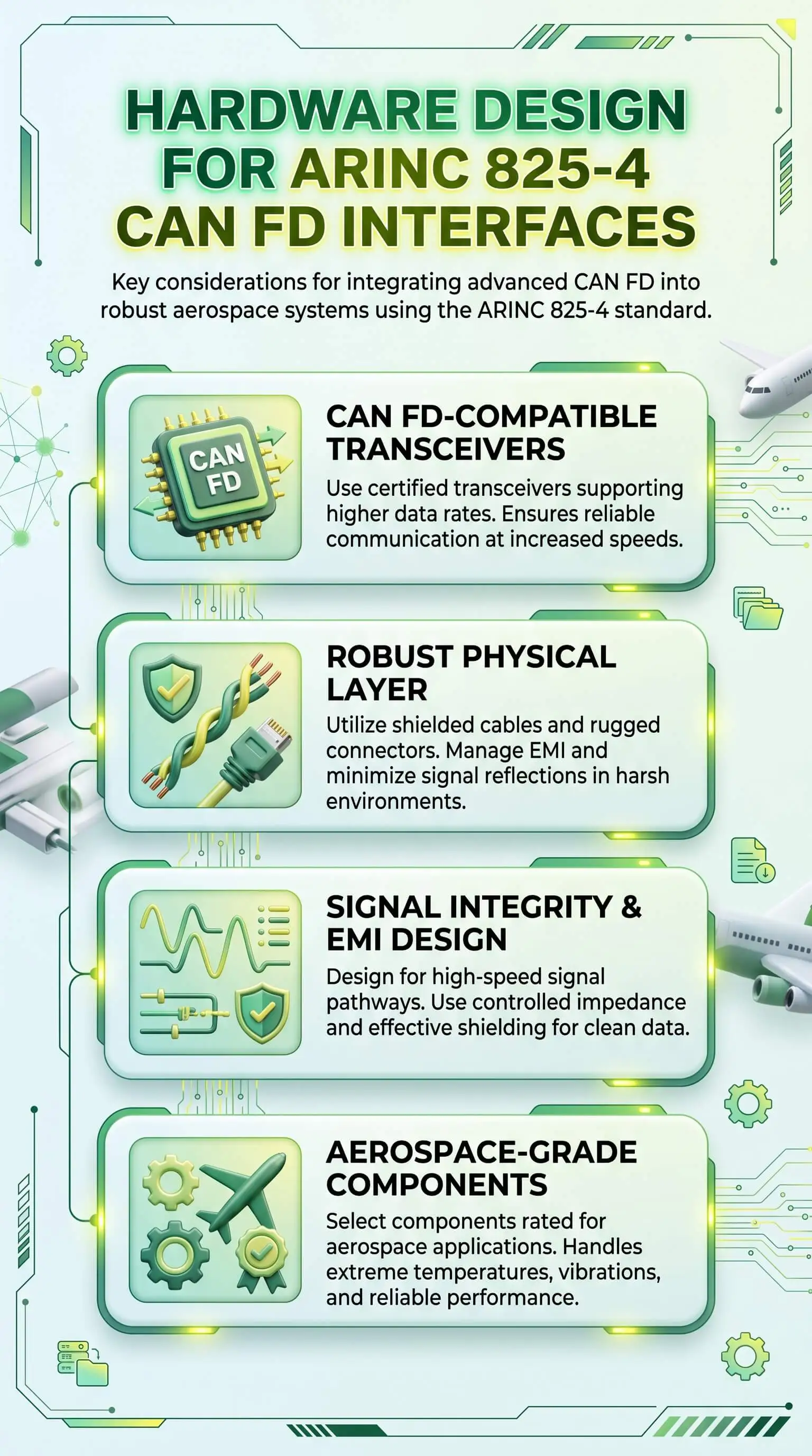
Pick the transceiver for the fast phase, not the slow one. A classic CAN transceiver won’t hold a clean eye at 2 Mbit/s and above, so the data phase decides your choice. You want tight transmit and receive delay symmetry, and on any topology that isn’t a clean point-to-point link, look hard at a CAN SIC (signal improvement capability) transceiver. SIC parts suppress the ringing that branches and stubs throw off, which buys margin for a real harness instead of an ideal one. Loop delay counts too, since a lower, well-specified loop delay lets the bus reach farther at a given rate. Whatever you pick, keep it compliant with the high-speed physical layer so it drops onto a standard two-wire bus and plays with the rest of your signal chain.
Termination, Topology, and Stub Length
CAN wants a linear bus, 120 ohms at each physical end, and nothing in between. Terminate the two far ends only. A stray resistor mid-bus throws reflections that close the eye. Keep stubs short, because every branch is a reflection point, and the faster the data phase runs the less stub you can afford. Watch node count and the capacitive load each node adds, since both drag on rise and fall times. When the airframe forces an awkward topology on you, that’s where SIC transceivers and a slightly lower data-phase rate earn their keep.
Signal Integrity and Bit Timing in the Fast Phase
CAN FD runs separate bit timing for the arbitration and data phases, so set the sample point for each one on purpose. Don’t let a tool default it. Oscillator tolerance tightens as the data rate climbs, so budget clock accuracy against the rate you actually plan to run. Account for propagation delay around the full loop, transceiver included, and leave phase margin for the asymmetries a built harness hands you. None of this is exotic. At 4 Mbit/s, though, the timing budget is tight enough that a guess shows up as bit errors on the bench.
Isolation, Grounding, and EMI Protection for Airborne Use
Avionics hardware lives in a brutal electrical environment, so plan the protection early. Galvanic isolation between the controller and the bus keeps ground differences from corrupting data and shields the node. Common-mode chokes tame the common-mode noise a CAN pair picks up, and TVS and ESD devices guard the transceiver pins against transients. Use shielded twisted pairs with the right characteristic impedance, and treat grounding as a design decision rather than an afterthought. Then qualify the result to DO-160 for temperature, altitude, vibration, EMI, and the lightning categories your installation calls for, using a data bus fault isolation tester where validation and troubleshooting demand precise bus-level fault insight. That’s the bar an airframe holds you to.
Redundancy, Fault Detection, and Certifiability
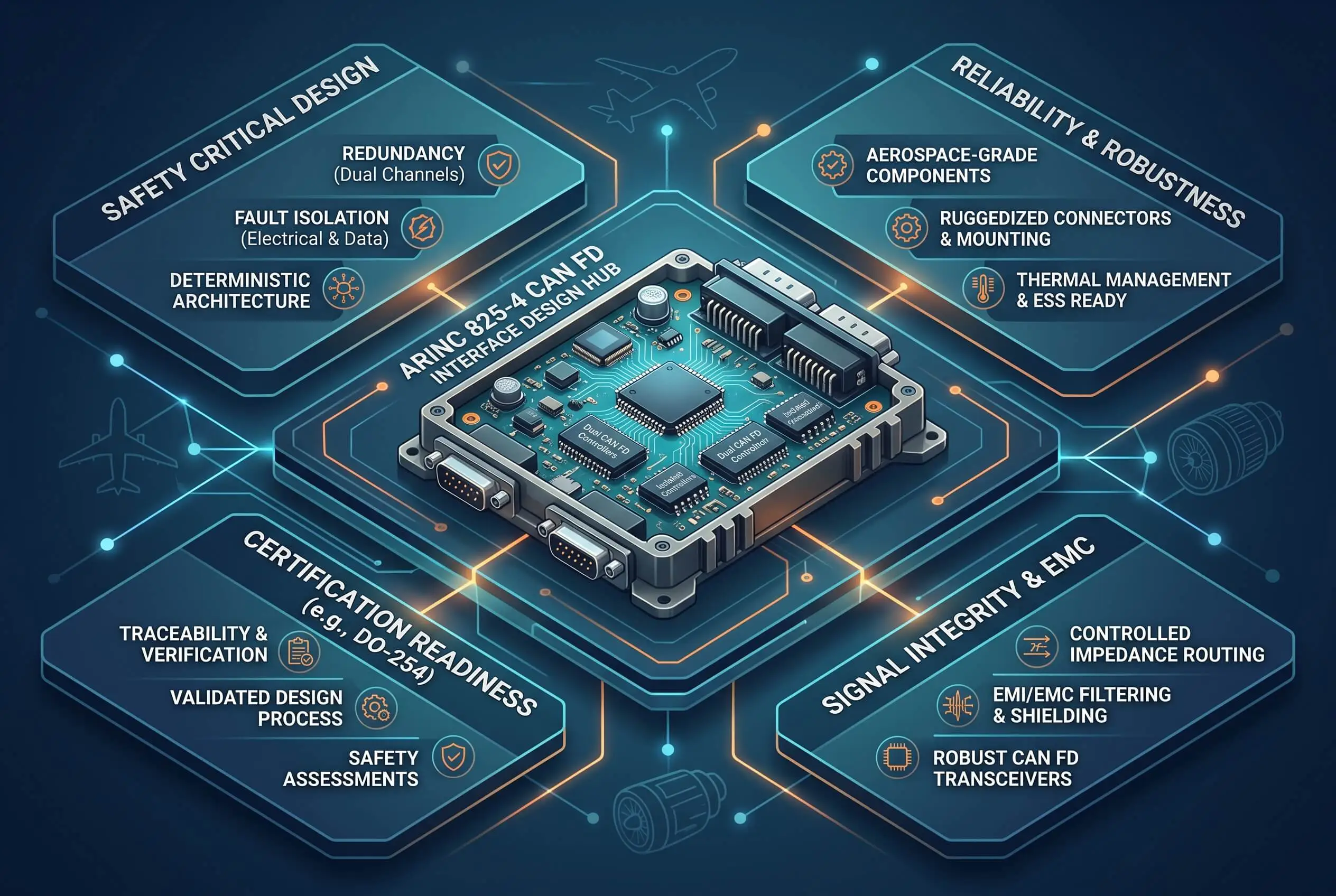
Safety-critical links often run redundant or dual buses so one failure can’t take the function down. The failures that eat schedule are the intermittent ones, which is why physical-layer health monitoring and wire-fault location are worth designing in from the start. A bus that reports an open, a short, and roughly where it sits turns a multi-day fault hunt into a guided repair. Plan for certification at the first schematic, not the last review. Hardware built to DO-254, with DO-178 for any associated software, can certify up to Design Assurance Level A, and a controller built to certify saves the months of rework an uncertifiable part forces later. An IP core is what makes this practical. A Bosch-compliant CAN, CAN FD, and ARINC-825-4 core delivered as a VHDL netlist drops into your FPGA or ASIC, works with any COTS transceiver, and keeps you independent of a single silicon vendor.
“The interfaces that cause a program the most pain are rarely the ones that fail outright on the bench. They’re the data-phase eye that looked fine until the production harness added a stub, and the intermittent short no continuity check could catch. After twenty-five-plus years of fielding databus hardware, we design the CAN FD physical layer for the harness we’ll actually fly, not the one on the schematic, and we build the bus to report its own electrical health so the failures show themselves the moment they happen.”
7 Essential Resources
Specifying an ARINC 825-4 CAN FD interface means reading across the protocol, the physical layer, the airborne environment, and the certification bar. These are the seven sources we point engineers to.
1. The ARINC 825-4 Standard Itself
The avionics CAN standard, currently at Supplement 4, which adds CAN FD and defines the messaging structure aircraft systems use. Start here to see what ARINC 825-4 inherits from CAN and what it adds on top. Source: ARINC 825-4, General Standardization of CAN Bus Protocol for Airborne Use (SAE ITC).
2. The CAN Data Link and Frame Foundation
The standard that defines the classic and CAN FD frame formats, including the 1 Mbit/s, eight-byte classic frame and the higher-rate, 64-byte FD frame your data phase relies on. Source: ISO 11898-1:2024, Road vehicles — Controller area network (CAN) — Part 1.
3. CAN FD Physical Layer Design Guidelines
CAN in Automation’s design guidance for the FD physical layer, with the formulas for propagation delay and phase margin and the topology recommendations that keep a fast data phase reliable. Source: CiA 601 series: CAN FD guidelines and recommendations.
4. Transceiver and Topology Options
A clear map of high-speed and SIC transceiver types, the bit rates each supports, and how topology choices shape what you can reach. Source: CiA: Physical layer options.
5. How Signal Improvement Capability Works
A transceiver maker’s walk-through of how SIC suppresses ringing, and why tighter timing symmetry and lower loop delay extend a real network. Source: Texas Instruments white paper: How Signal Improvement Capability Unlocks CAN FD (SLLA581).
6. The Airborne Environmental Bar
The environmental conditions and test procedures airborne equipment has to clear, including temperature, altitude, vibration, EMI, and lightning. Design your protection and isolation to it. Source: RTCA DO-160, Environmental Conditions and Test Procedures for Airborne Equipment.
7. Hardware Design Assurance for Certification
The FAA’s best-practices guidance for airborne electronic hardware design assurance under DO-254 and ED-80, useful when you plan certification before you cut a board. Source: FAA AC 00-72, Best Practices for Airborne Electronic Hardware Design Assurance.
These seven resources show why specifying an ARINC 825-4 CAN FD interface requires more than protocol selection: engineers have to account for frame behavior, physical-layer limits, transceiver topology, airborne environmental testing, and certification discipline, the same way they would when selecting MIL-STD-1553 transceivers and transformers for reliable mission-critical aircraft data buses.
Supporting Statistics
The case for getting an avionics CAN FD interface right isn’t abstract. Three numbers frame it.
A Large, Long-Lived Installed Base
The FAA’s latest survey put the active U.S. general aviation fleet at about 213,756 aircraft in 2024, each carrying multiple databus links. A new interface has to interoperate with that fleet, which is why protocol compliance and certifiability matter as much as raw speed. Source: FAA Aerospace Forecast, Fiscal Years 2026–2046.
The CAN Node Count Keeps Climbing
Registered light-duty electric vehicles in the United States grew from under 100,000 in 2012 to more than 3 million by 2022. Every one rides on CAN and CAN FD with more electronic control units and more nodes, and the same bandwidth pressure pushes avionics and ground-vehicle programs toward FD. Source: U.S. Energy Information Administration, Use of Energy for Transportation: Electric Vehicles.
Bus-Level Security Isn’t Optional
In operational testing between 2012 and 2017, the U.S. Government Accountability Office reported that defense testers found mission-critical cyber vulnerabilities in weapon systems under development and often operated undetected with relatively simple tools. On a data bus, that’s the argument for authenticating traffic and monitoring the physical layer instead of trusting the perimeter. Source: U.S. GAO, Weapon Systems Cybersecurity (GAO-19-128).
Final Thoughts and Opinion
Here’s where we land after twenty-five-plus years of building this hardware. The fast data rate is the part everyone fixates on, and it’s the part that matters least.
Speed is the easy part. Reaching 4 Mbit/s on CAN FD is table stakes. The work that pays off is holding the data-phase eye on a real harness, isolating and protecting the interface, and finding a wire fault before it grounds a platform.
Certifiability belongs in the first design review, not the last. A core and a physical layer built to DO-254 save the rework a faster-but-uncertifiable part forces on you later.
Design security and health monitoring into the bus, not around it. A bus that authenticates its own traffic and reports its own electrical state is far harder to fool than a perimeter.
If your roadmap touches avionics, defense ground vehicles, or automotive control, the question isn’t whether to engineer the CAN FD interface carefully. It’s how early you start.
Frequently Asked Questions
What is the difference between CAN bus, CAN FD, and ARINC 825-4?
Classic CAN (CAN 2.0B) runs up to 1 Mbit/s with an eight-byte payload. CAN FD keeps the same arbitration but raises the data phase to 4 Mbit/s and the payload to 64 bytes. ARINC 825-4 is the avionics higher-layer standard built on CAN, currently at Supplement 4, which added CAN FD.
What data rate can an ARINC 825-4 CAN FD interface reach?
Up to 4 Mbit/s in the data phase, with the arbitration phase running at the classic rate. The rate you actually hold depends on your topology, cabling, transceiver, and timing budget.
How does termination differ for CAN FD versus classic CAN?
The rule is the same, 120 ohms at each physical end, but CAN FD forgives less. Reflections from mid-bus termination or long stubs that a slow classic bus tolerated will close the eye in the fast data phase.
Which standards govern certifying a CAN FD interface for avionics?
Plan to DO-254 for the airborne electronic hardware and DO-178 for associated software, with environmental qualification to DO-160. Built correctly, the interface can certify up to Design Assurance Level A.
Can one controller or IP core support classic CAN, CAN FD, and ARINC 825-4?
Yes. A Bosch-compliant core can support all three from one design, with 11-bit and 29-bit identifiers, delivered as a VHDL netlist that works with any COTS transceiver and aligns with the same FPGA/ASIC integration discipline expected from MIL-STD-1553 IP cores.
Ready to Specify Your ARINC 825-4 CAN FD Interface?
Put a Bosch-compliant, DO-254-certifiable CAN, CAN FD, and ARINC-825-4 core into your next FPGA or ASIC, whether the program supports an aircraft platform, defense system, or specialized training environment such as a private school avionics lab. Talk to a Sital field engineer or request an evaluation, and we’ll match the core’s configuration to your protocol mix, certification target, and topology before you commit.